
Q: What springs do I need for my race car?
To answer that, you need to have three important pieces of information.
- Driver
- Track
- Car
That may sound obvious, but think about this, one driver can get in to the race champion’s car and do a miserable lap. And the CAR just won the race at that TRACK. The difference? The DRIVER. Assuming the drivers are of similar build so as not to change the weight balance of the car. The race champion had a different ‘feel’ for the suspension dynamics at that track for that car, compared to the second driver.
There are other basic factors to consider outside of the three just mentioned. They are the "set" load (or preloaded weight) of each wheel, shock type, caster & camber, tire choice (width and compound) and body aerodynamics. You may have a preference for a little more body roll through a corner, therefore requiring a lighter spring rate, and possibly an adjustment to the shock’s dampening rate. If you prefer less body roll through a corner, you would require a stiffer spring for that car in that situation.
But to do any of that, you need to understand the preloaded or “set” weight on the spring then factor the Spring Rate and Total Travel to determine if you are over stressing the spring.
So, a 12” Free Length spring with a Coil Bind of 5.75” gives 6.25” of Total Travel, therefore it can handle 3125 lbs. of weight (6.25” x 500lb/in) before it becomes over stressed. If the Preload Length 1.5” (750 lbs) you are left with 2375 lbs. of available cornering load, but you also will have 4.75” of travel. Quite a considerable distance in road racing, but not necessarily a lot for rally and rally-cross.
So, you can see that the question “What Springs do I need for my race car” requires many variables to be answered before a good answer can be given.
Our friends at Eibach have a good set of diagrams and equations to sort out all the intricate details.
How do I measure brake clearance?
Before you buy, regardless of wheel size, you must confirm brake system to wheel clearance before purchasing a Brembo Performance system.
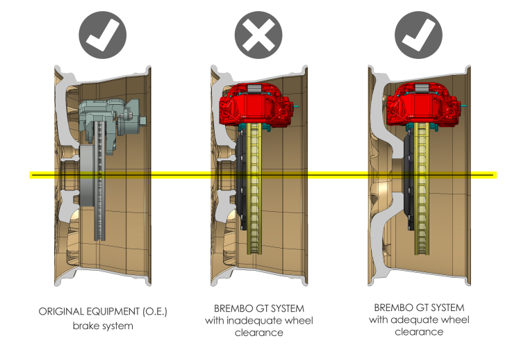
These CAD drawings represent the clearance of an Original Equipment (left) brake system compared to a GT system with inadequate clearance (middle), and one with proper clearance (far right).
Brembo Performance brake systems are always designed to maximize wheel fitment. However larger components are often required to meet performance parameters determined by Brembo engineers, so it may be necessary to utilize a wheel spacer or to upgrade to an aftermarket wheel with adequate clearance. There are a number of variables that can affect wheel clearance including wheel diameter, wheel offset, and wheel design.
In order to determine if a wheel has adequate clearance, please follow the instructions below or download a printable copy of these instructions by clicking here.
PRINTING THE TEMPLATE
STEP 1: Look up your application (Year/Make/Model search) on www.racetechnologies.com.
STEP 2: Select your brake system.
STEP 3: Download or open the PDF document listed under Wheel Clearance information. Note: All Brembo GT/GT-R systems have a specific corresponding wheel clearance diagram (brake profile cross section).
STEP 4: Print out the document, but be sure to make sure you’re printing at full scale (1:1 or at 100% size). There’s a ruler on the bottom right-hand side of the page to compare it with.
STEP 5: Cut out the shape of the template to include the caliper, bell, and disc.
Optional: You may want to back the cut-out with a piece of cardboard or foam core to make sure that the template is sturdy enough to get a proper gauge of your wheel clearance.
MEASURING YOUR WHEEL
STEP 1: Remove a wheel.
STEP 2: Place the wheel carefully on its face and measure out the A/B/C dimensions with a straight edge or create a template from the clearance diagram.
STEP 3: If using a clearance diagram attached to tag board as a template, be sure to double check that the template retains the actual dimensions from the original diagram.
STEP 4: Allow 3mm in all directions from the caliper to the wheel.
STEP 5: If the caliper contacts the inner wheel spokes, a wheel spacer may be used to move the wheel out away from the caliper. When using spacers, we recommend only considering high quality hubcentric spacers (and longer wheel bolts/lugs when needed). It is also important to confirm that the wider track will allow the tire to clear the fenders in all positions.
EXAMPLE BELOW
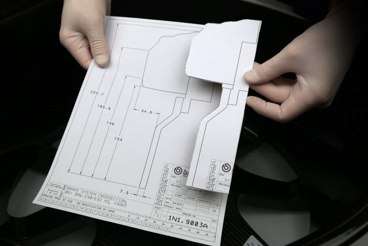
We are using part #1n1.9003A (a 2013 BMW M3) for our example.
The kit number is shown on the lower right, and all measurements are shown in millimeters. The diagrams are shown at full scale, but once they have been printed these measurements must be confirmed before use. We colored in the CAD drawing to help make it easier to understand the brake assembly cross section. The red area represents the rotated profile of the caliper, the dark grey colored area is the bell, and the silver area is the disc.
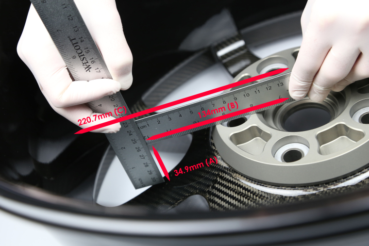
The A dimension is 34.9mm The B dimension is 134mm The C dimension is 220.7mm
In this example, the clearance diagram has the center of the wheel marked with a yellow highlighter. If you rotate the previous diagram and set it into the wheel, it would look like the diagram above that includes a wheel cut-away. That same yellow line is represented by the dashed line below. The drawing above is a cut-away of a GT system inside of a wheel on its face.
All Brembo Performance systems are custom packaged to order, so they cannot be returned due to wheel fitment which is why it’s very important to verify brake and wheel fitment before placing your order.